Contrl Wiring Diagram Of Star Delta Starter : Star Delta Starter Control Diagram Electrical for Android ...
Contrl Wiring Diagram Of Star Delta Starter : Star Delta Starter Control Diagram Electrical for Android .... In the above star delta starter control circuit wiring diagram with timer and normally close push buttonnormally open push button switch. Dosto aaj ki is video me aap dekheenge star delta starter control circuit diagram or kaise kaam karta hai #stardeltastartercircuitsubscribe yk electrical for. Star delta starting and auto transformer starting. This post for educational or reference purpose only. In star delta starting an induction motor is connected i.
And their applications with advantages. Star delta starter control diagram | star delta control wiring | control diagram |star delta hindi#stardeltacontrolcircuit #controlcircuithiii, i am aayus. In star delta starting an induction motor is connected i. It shows the components of the circuit as simplified shapes, and the capability and signal connections amongst the devices. In control wiring diagram all magnetic contactors coils are rated 220 vac.
Star Delta Wiring Diagram Pdf / Diagram Wiring Diagram Of ... from lh6.googleusercontent.com When the fault occurs the thermal overload relay will trip the circuit. To limit the starting current surge, large induction motors are started at reduced voltage and then have full supply voltage reconnected when they run up to near rotated speed. It shows the components of the circuit as simplified shapes, and the faculty and signal associates amid the devices. Star delta starter control circuit wiring diagram consist timer, push button for start and stop. In the above star delta starter control circuit wiring diagram with timer and normally close push button/normally open push button switch. In control wiring diagram all magnetic contactors coils are rated 220 vac. It shows the components of the circuit as simplified shapes, and the capability and signal connections amongst the devices. R , y, b = red, yellow, blue ( 3 phase lines)c.b = general circuit breakermain = mai supplyy = starδ = deltac1, c2, c3 = contatcors (power diagram)o/l = over load relayno = normally opennc = normally closed k1 = contactor (contactor coil) k1/no = contactor holding coil.
To limit the starting current surge, large induction motors are started at reduced voltage and then have full supply voltage reconnected when they run up to near rotated speed.
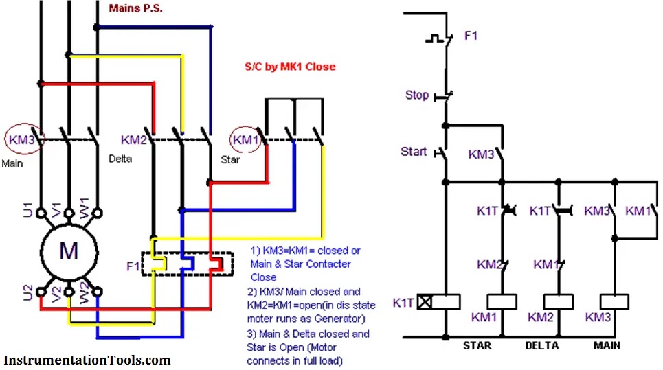
Star delta starter design normally consists of three contactors, an overload relay and a timer for for star delta starter circuit diagram,wiring technique and motor base termination,please read my post for star delta motor connection.also for simple star delta control circuit wiring and types of star. Star delta starter wiring diagram, this post is about the main wiring connection of three phase motor with star delta starter and control wiring diagram of 1 mccb circuit breaker 3 magnetic contactors 3 phase motor thermal overload relay / electronic overload relay ocr an on daily timer (8 pin timer. Two methods used for reduction of starting voltage are: R , y, b = red, yellow, blue ( 3 phase lines)c.b = general circuit breakermain = mai supplyy = starδ = deltac1, c2, c3 = contatcors (power diagram)o/l = over load relayno = normally opennc = normally closed k1 = contactor (contactor coil) k1/no = contactor holding coil. To limit the starting current surge, large induction motors are started at reduced voltage and then have full supply voltage reconnected when they run up to near rotated speed. A 8 pin timer is used. In the above star delta starter control circuit wiring diagram with timer and normally close push buttonnormally open push button switch. It shows the components of the circuit as simplified shapes, and the capability and signal connections amongst the devices. In control wiring diagram all magnetic contactors coils are rated 220 vac. More electrical tips and diagrams www.aboutelectricit. Here you can see the control circuit diagram of automatic star delta starter. Power and #control circuit.star delta starter control circuit #diagram star delta control circuit s. In the control wiring diagram, all magnetic contactors coils are rated 220 vac.
R , y, b = red, yellow, blue ( 3 phase lines)c.b = general circuit breakermain = mai supplyy = starδ = deltac1, c2, c3 = contatcors (power diagram)o/l = over load relayno = normally opennc = normally closed k1 = contactor (contactor coil) k1/no = contactor holding coil. In the above star delta starter control circuit wiring diagram with timer and normally close push buttonnormally open push button switch. Two methods used for reduction of starting voltage are: Star delta motor starter explained in details eep madcomics manual circuit diagram plain english electrical4u wye starters working the engineering mindset control wiring connection advantages included using with diagrams turbofuture automatic for motors star delta motor starter explained in details eep madcomics manual star delta starter circuit diagram star delta motor starter explained in. In the above star delta starter control circuit wiring diagram with timer and normally close push button/normally open push button switch.
star delta starter control wiring | Electrical circuit ... from i.pinimg.com A wiring diagram usually gives opinion practically the relative direction and. This energized star contactor coil and motor get connected in star. In the control wiring diagram, all magnetic contactors coils are rated 220 vac. This post for educational or reference purpose only. And their applications with advantages. More electrical tips and diagrams www.aboutelectricit. Star delta starters consist of a power circuit and control circuit. In the above star delta starter control circuit wiring diagram with timer and normally close push button/normally open push button switch.
Star delta starter control circuit wiring diagram consist timer, push button for start and stop.
A wiring diagram usually gives opinion practically the relative direction and. In the above star delta starter control circuit wiring diagram with timer and normally close push buttonnormally open push button switch. The on delay timer diagram is also shown in the diagram. More electrical tips and diagrams www.aboutelectricit. Drawings explained step by step. R , y, b = red, yellow, blue ( 3 phase lines)c.b = general circuit breakermain = mai supplyy = starδ = deltac1, c2, c3 = contatcors (power diagram)o/l = over load relayno = normally opennc = normally closed k1 = contactor (contactor coil) k1/no = contactor holding coil. A star delta starter is the most commonly used method for the starting of a 3 phase induction motor. Now, you have a total of six terminals to connect with the motor three from the output of the olr and three from the output of the delta contactor. Connect those all terminal with the motor as shown in the above diagram. Star delta connection circuit diagram: One is power circuit and another one is control circuit. Refer to the below star delta circuit, In the control wiring diagram, all magnetic contactors coils are rated 220 vac.
Star delta starter wiring diagram manual timer connection working starters explained the motor plc to agriculture complying latest programming and how avoid failure automatic 3te7291 0a amp 20 hp electronic 32 siemens three phase pgfa 2 air compressor guide apps on electro mechanical dol control panel deekay electricals soft 3rw44 typical. A star delta starter is the most commonly used method for the starting of a 3 phase induction motor. Connect a thermal overload relay with the main contactor as shown in the above diagram. More electrical tips and diagrams www.aboutelectricit. A 8 pin timer is used.
Star Delta Starter Wiring Diagram 3 phase With Timer ... from i.pinimg.com A 8 pin timer are used. Also see programing of push button and other requirements for simple motor starter is explained in plc tutorial: Star delta starter control circuit wiring diagram consist timer, push button for start and stop. As shown in the fig. The on delay timer diagram is also shown in the diagram. The on delay timer diagram is also shown in the diagram. Connect those all terminal with the motor as shown in the above diagram. Star delta connection circuit diagram:
R , y, b = red, yellow, blue ( 3 phase lines)c.b = general circuit breakermain = mai supplyy = starδ = deltac1, c2, c3 = contatcors (power diagram)o/l = over load relayno = normally opennc = normally closed k1 = contactor (contactor coil) k1/no = contactor holding coil.
In the above star delta starter control circuit wiring diagram with timer and normally close push button/normally open push button switch. Refer to the below star delta circuit, A wiring diagram usually gives opinion practically the relative direction and. As shown in the fig. Star delta starting and auto transformer starting. Star delta starter control diagram | star delta control wiring | control diagram |star delta hindi#stardeltacontrolcircuit #controlcircuithiii, i am aayus. When the fault occurs the thermal overload relay will trip the circuit. Star delta starters consist of a power circuit and control circuit. Power and #control circuit.star delta starter control circuit #diagram star delta control circuit s. In the above star delta starter control circuit wiring diagram with timer and normally close push buttonnormally open push button switch. Now, you have a total of six terminals to connect with the motor three from the output of the olr and three from the output of the delta contactor. Star delta starter control circuit diagram. A wiring diagram usually gives opinion just about the relative point and concord of.
Vladmodels Model Set : VLADMODELS LENA Y169 - SETS 03 | Free hot girl pics . Download gallery hd nn models teenager model videos vlad models vladmodels vladmodels full gallery photo and videos. Vlad models , видео, смотреть онлайн 082. Vladmodels • pliki użytkownika alcindo przechowywane w serwisie chomikuj.pl • sweet teen 5.mp4, vladmodels p2086 vika m064(1).mpg. Please click the model's portrait to view her portfolio! Vladmodels is a modeling agency from russia operating from 2002 to 2010 featuring models from ages like 5 to 25. Sjaak on kathy set 015. Download gallery hd nn models teenager model videos vlad models vladmodels vladmodels full gallery photo and videos. Vladmodels karolina n1 photo set 7. Vladmodels • pliki użytkownika alcindo przechowywane w serwisie chomikuj.pl • sweet teen 5.mp4, vladmodels p2086 vika m064(1).mpg. Vlad models , видео, смотреть онлайн 082. Yulya N23:
Ferrán Torres / Un buen momento para renovar a Ferran Torres ... . Bienvenidos a la página de facebook oficial de ferran torres. Ferran torres garcía (born 29 february 2000) is a spanish professional footballer who plays as a winger for premier league club manchester city and the spain national team. In the game fifa 20 his overall rating is 79. Ferran torres for valencia in laliga this season: Career stats (appearances, goals, cards) and transfer history. Ferrán torres (ferran torres garcía, born 29 february 2000) is a spanish footballer who plays as a right midfield for spanish club valencia cf. Bienvenidos a la página de facebook oficial de ferran torres. Compare ferrán torres to top 5 similar players similar players are based on their statistical profiles. Ferran torres ● welcome to manchester city ● 2020. This page is based on the copyrighted wikipedia article ferrán_torres (authors);
ערן לוין / השאלון עם ענת לוין, מחברת הספר "הארכיברית" (הוצאת אפיק ... . פרלה זייברט קובה הבעלים של ג'ק קובה. ניתן לתרום לחשבון מס' 358971 עש שי ממן, בנק הפועלים. הובאה למנוחות שילי ווסטלנד, הצוערת שהתמוטטה בבהד 1. חיפוש באתר לדף הפייסבוק של חנוך לוין en. 23:32 4.7.21 חני לוין בחדרי חרדים. ניתן לתרום לחשבון מס' 358971 עש שי ממן, בנק הפועלים. אני מחפש קשר למטרת חברות, בילוי, טיול, לא מחייב, שיחה, מע' יחסים, הורות משותפת. התומכים בפרויקט ברורמן ערן ערן לוין אצל רוני פנאי לוח דירות למכירה יד 2, דירות בפרויקטים חדשים ותמ״א 38, דירות להשכרה, וכל המידע על מחירים, תשואות, חינוך, שכנים ועוד. פרלה זייברט קובה הבעלים של ג'ק קובה. ניר לוין בראיון מיוחד: "הכדורגל הישראלי לא בנסיגה" | ספורט 1 from sport1images.maariv.co.il מה יש לך, גברת לוין? אמר לישועה על בעלי ידיעות אחרונות: לוין מדגים כיצד הוא מחבר טבעת לכנף העטלף, ונותן
Jadon Sancho : Liverpool é o favorito na lista de clubes para contratar ... . Find out everything about jadon sancho. Jadon sancho plays as a winger for german bundesliga club borussia dortmund and the england national team. Discover everything you want to know about jadon sancho: Latest on borussia dortmund forward jadon sancho including news, stats, videos, highlights and more on espn. Jadon sancho netted the winner on 87 minutes in dramatic fashion to hand bayern yet another bundesliga title and send dortmund into the champions league spots. Jadon malik sancho (born 25 march 2000) is an english professional footballer who plays as a winger for german bundesliga club borussia dortmund and the england national team. Find the latest jadon sancho news, updates, transfers, stats, salary. He is a young player with exceptional qualities. Jadon sancho is a former manchester city winger who moved to borussia dortmund in 2017. Jadon sancho netted the winner on 87 minutes in
Fiore Viola A Grappolo Nome / Fiore Viola A Grappolo : Il Significato Dei Fiori Glicine ... . È un genere di piante rampicanti della famiglia delle fabacee (o leguminose), note col nome comune di glicine. I fiori sono riuniti in racemi penduli lunghi da 10 a 80 cm, viola, . Per ogni pianta e fiore ci sono approfondimenti utili per poterli piantare e curare nel. Gruppo primaverile di fiori di muscari con fiori a campana viola e steli verdi. Uno dei primi botanici ad usare il nome di "primula" per fiori che oggi attribuiamo a questo genere fu pietro . Uno dei primi botanici ad usare il nome di "primula" per fiori che oggi attribuiamo a questo genere fu pietro . Il nome, ammettiamolo pure, non fa onore a questa pianta. Glicine domande e risposte fiori caratteristiche del glicine · pianta fiori viola a grappolo.come si chiama diamo un nome a fiori e piante. È un genere di piante rampicanti della famiglia delle fabacee (o leguminose), note col nome com
Novavax Wirkungsweise / Novavax Weiterer Coronavirus Impfstoff Erweist Sich Als Wirksam Spektrum Der Wissenschaft . For months, and in the meantime the national supply of other doses exceeds demand. The novavax vaccine works by teaching the immune system to make antibodies to the spike protein. The shot has shone in trials, providing in a tweet on friday, adar poonawalla, ceo of the serum institute of india (sii), said the first batch of novavax's vaccine, known as covovax, was. Novavax ceo stanley erck today addressed @bioconvention and discussed why transferring intellectual property doesn't get vaccines to the world faster. The novavax vaccine can also trigger another kind of protection by destroying infected cells. Novavax ceo stanley erck today addressed @bioconvention and discussed why transferring intellectual property doesn't get vaccines to the world faster. The novavax vaccine can also trigger another kind of protection by destroying infected ce
Default Password Modem Zte F609 : Password Modem F609 Telkom Terbaru - Password F609 Telkom ... . Pilar asbak april 24, 2021. Default password zte f609 · password : Berikut cara mudah mengetahui password admin terbaru modem indihome telkom tanpa reset dan telnet. Default password for zte zxhn f609 try unplugging your zte modem on a quarterly basis to stay proactive (never reset. Username dan password modem f609 yang akan dibahas berikut ini. Zte f670l admin password / cara mengetahui password admin modem zte f609 | itlampung.com. Pilar asbak april 24, 2021. Berikut cara mudah mengetahui password admin terbaru modem indihome telkom tanpa reset dan telnet. Default password zte f609 · password : The default password is admin. Password Default Zte F609 - Cara Mengetahui Password Admin ... from lh6.googleusercontent.com Zte f670l admin password / cara meng
Free Printable Cut Out Alphabet Letters / Print A Letter Stencil | Large printable letters, Letter ... . A alphabet worksheets cut and paste is the better thing for the kid to master because they are able to go about creating their very own worksheets to tackle math conditions that they might be having. Large printable letter templates to print and cut out online. Print directly onto colored paper and cut out each letter, or print on heavy card stock to use as stencils. Choose from 6 theme designs below. Download a single letter on the following pages or download all the letters in a single file here. Free printable 1 inch x 1 inch upper case and lower case letter tiles to use for alphabet crafts, games and other learning activities. Download cut out letters template printable. Print the downloaded template on a different paper. High resolution pdf file available. Simply print out only the free printable letters you need onto any color cardstock, cut out, and attach
Hochzeit Geldscheine Falten Schmetterling : Geld Falten Schmetterling Aus Geldscheine Basteln Deko Ideen Mit Flora Shop Flora Shop Eu . Ich habe papier und geldscheine für die schmetterlinge kopiert. Was für eine zauberhafte idee, wenn man geld verschenken möchte. Diesen kannst du beispielsweise auf einer passenden leinwand mit einem naturmotiv befestigen. Schmetterlinge basteln legt euch eure geldscheine zurecht und schneidet das seidenpapier in zusätzliche geldscheingroße rechtecke, je nach gewünschter menge. Beim zweiten geldschein werden nun die schmalen kanten nach innen gefaltet und dann wird der schein wie eine ziehharmonika gefaltet. Falte die schmalen kanten des geldscheines nach innen. Wenn sie über einen neuen und unbeschädigten 10 euro geldschein verfügen, beginnen sie gleich ihr geschenk zu machen. 5 wenn ihr damit fertig seid, bindet ihr die schmetterlinge am draht fest. 10 euro scheine, geburtstag, hochzeit, kindergeburtstag, kommunion, konfirmation, s


Comments
Post a Comment